1сђЂCHN-F1
In this example, Dimaxer software is used to simulate the wall-resolved LES of the flying wing model under the flight condition of Mach number 0.9. The small aspect ratio flying wing aircraft is significantly different from the traditional fighter aircraft due to its geometric characteristics such as the removal of external protrusions such as flat tail and vertical tail, the geometric characteristics of the whole fuselage as the lift surface, and the aerodynamic characteristics of the wing surface and the fuselage, large leading edge sweep angle, small aspect ratio, and no vertical stabilizer.
Schematic diagram of the geometric model of the CHN-F1 flying wing standard mold
2. Calculate the grid
The mesh model is a half-mode.
The mesh type is a full hexahedral mesh with a first layer mesh height of 0.038mm and a Y Plus of about 10.
The aspect ratio of the mesh near the wall is less than 200, and the number of half-mode grids is about 1.76 million.
CHN-F1 flying wing standard model calculation grid
3. Boundary conditions and initial field
Boundary condition information: The object surface of the model is a viscous solid wall boundary, the Y=0 plane is a symmetrical boundary, and the outer boundary is set to the far-field boundary condition, and the initial field is calculated as a uniform initial field.
4. Aerodynamic coefficient
The aerodynamic parameters compared with the test are mainly Ma=0.9, the lift coefficient Cl, drag coefficient Cd and pitching moment coefficient Cm of the flying wing at different angles of attack, and the change trend is shown in the figure below.
Variation curves of the lift coefficient, drag coefficient and pitching moment coefficient of the CHN-F1 flying wing with the angle of attack
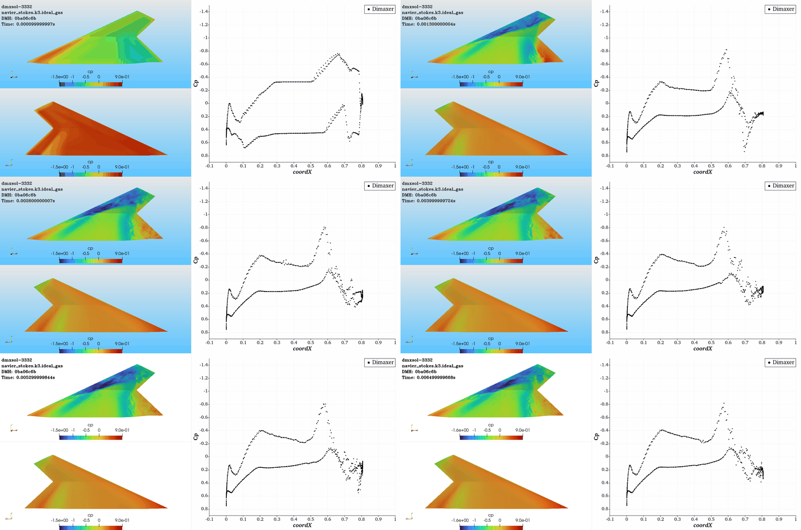
5. Surface pressure distribution
Surface pressure coefficient distribution of CHN-F1 flying wing at 12 degrees angle of attack:

6. Velocity flow field
CHN-F1 flying wing 10 degree angle of attack symmetrical surface velocity field:
 CHN-F1 flying wing 12 degrees angle of attack symmetrical surface velocity field:

7. Instantaneous vortex structure
Instantaneous vortex structure of CHN-F1 flying wing with 12 degrees angle of attack (Q criterion, flow direction velocity coloring):

8. Computing efficiency
In this example, the calculation grid of each working condition point is 1.76 million, the fourth-order precision is solved, the solution point is about 112.64 million, and the calculation is 0.025s and about 10 flow cycles to stability.
With 4 4090 GPU cards, 3 GPU hours are required per flow cycle. It takes about 7.5 hours to complete the calculation for each case.
Rankyee у▓цICPтцЄ2023060583тЈи