1. ONERA M6 three-dimensional airfoil verification example
As a typical transonic example, the M6 wing is one of the standard models for CFD software assessment.
The purpose of this model is to evaluate the ability of CFD software to simulate the complex flow of transonic shock/shock wave and shock/surface layer interference.
The M6 example is selected to demonstrate the ability of overset mesh to calculate transonic velocity in implicit large eddy simulation.

1.1 Calculation Description
1.1.1 Calculation Status:

1.1.2 Calculate the grid:
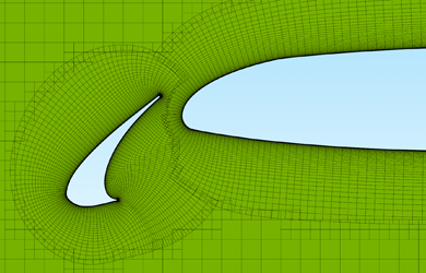
The computational mesh adopts an Overset mesh, which is generated by the Mesh extrude function near the near wall, the first layer of the mesh is 0.03mm high, the y+ is about 10, and the background mesh of the outer and far-field areas near the wall is composed of an auto-filled structural hexahedron. The total number of grids is 2.7 million.


The total number of grids is about 2.7 million, including 1.2 million near-wall grids and 1.5 million background grids.
The object surface of the model is the viscous solid wall boundary, the Y=0 plane is the symmetrical boundary, and the outer boundary is set as the far-field boundary condition, and the initial field is calculated as the uniform initial field.


1.2 Calculation Results
1.2.1 Surface pressure coefficient distribution
The video of the transient calculation results is as follows:
The steady-state average results are as follows:

1.2.2 y/b = 0.44 symmetrical surface velocity field

1.2.3 Surface vortex structure

2. CHN-F1 flying wing overset grid
In the previous official account content: Dimaxer simulation example: CHN-F1 wing implicit large eddy simulation, we show the results of the CHN-F1 flying wing using a fully consistent (conformal) mesh using Dimaxer2023R2 large eddy simulation, this article introduces the calculation results of using the overset mesh under the same boundary layer mesh conditions, as a comparison to verify the consistency of the overset mesh and the conformal mesh.
2.1 Calculation Description
2.1.1 Computational Model

2.1.2 Computing the grid

2.2 Calculation Results
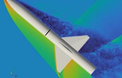
2.2.1 Overall flow field
The distribution of the surface pressure coefficient of the 12┬░ flying wing at the angle of attack is as follows:
overset grid
conformal grid
The distribution of the velocity field of the symmetrical plane in the center of the 12┬░ flying wing with an angle of attack is as follows:

As shown in the figure above, the overset mesh scheme generated by Dimaxer pre-processing can capture the wake development of the flying wing with higher accuracy due to the customization of the local encryption region, which indicates that the overset mesh meets the requirements of high-precision simulation and the actual simulation scene is more flexible and convenient.
2.2.2 Pneumatic power
Compared with the test and the conformal grid, the aerodynamic parameters are mainly Ma=0.9, and the lift coefficient Cl, drag coefficient Cd and pitching moment Cm of the flying wing at different angles of attack are shown in the figure below.


3. Summary
For the CHN-F1 verification example, the flow field distribution is basically the same in the calculation using overlapping mesh and conformal mesh, and the maximum error of the aerodynamic characteristic coefficient of each angle of attack is not more than 0.5%, which meets the mesh consistency requirements. Demonstrate the applicability of overlapping meshes in the analysis of typical transonic problems.
Rankyee ń▓żICPÕżć2023060583ÕÅĘ